Introduction
The plan is to make a box to play music from my music library. It must be incredibly simple to use (no buttons), but most of all it needs a VOLUME control.
Desing based an old Chronos CD/Radio alarm, but replace all electronics lot with a Raspberry pi and use some RFID tags – more later.
This is what the device looks like at the start:
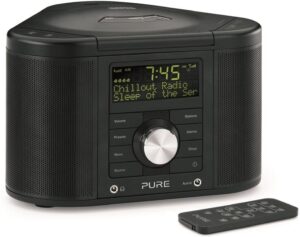
If all goes well it will look much the same at the end, but with a more snazzy display.
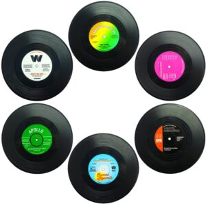
The plan is to rip the guts out (except for the speakers) and hide a Raspberry Pi inside. To use, pop open the CD lid, insert a RFID tag to select a folder full of music, eg: Blues/Classical/Pop/Vocal etc. The folder RFID tag will of corse be concealed in a vinyl record like one of these.
Its all controlled by the BIG SILVER KNOB on the front. Load a place mat and an folder full of appropriate music is selected at random. Close the lid and its starts playing. Turn the BSG with the lid open and it starts to scroll through available albums. Close the lid and the knob controls the volume. So simple, what could go wrong….
Components
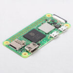
- Raspberry Pi Zero 2 W (£13.50)
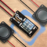
- Pirate Audio Digital Amp with display (£19.50)
- OR
Stereo 3.7W Class D Audio Amplifier – MAX98306 (No Display) and roll your own display.
-
Speakers 6 ohm/5 Watt (from radio)
- Power supply (£7.50)
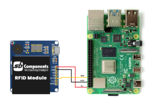
- RFID reciever
- RFID tags (Pack of 5 for £3.80)
- RFID reader:
- https://thepihut.com/products/nfc-hat-for-raspberry-pi-pn532 (£22.90) 3 interfaces SPI, UART, I2C
- https://thepihut.com/products/rfid-breakout-board (£15) USB2/UART
It looks like its important to use the version 2 for the raspberry pi zero because it has a bit more CPU than the original version. Wifi will be on and the pi running ‘headless’. When it requires attention I can connect in over the wifi. The Pirate Radio Amp is powered by the RPi which simplifies things a bit. Its a Class D amplifier which makes it very efficient. Its supposed to be used with 8 ohm speakers and the old speakers are 6 ohm. I doubt it matters much. Its the power handeling that counts (unless you want to blow them up!). The Pirate Audio board includes a display and four buttons. The display is a bit smaller than I would like, but may fit in the front pannel display above the BIG SILVER KNOB.
The Pirate Audio board also includes four buttons. By default they are Play/Pause/Volume Up/Down but can be reconfigured. I will need to figure out how to use the BIG SILVER KNOB to control the system.
I also have a small 3.5″ display. I may fit it inside the CD compartment to help scroll through the albums. Not sure at present if it is possible to have two boards connected to the RPi at the same time.
Software
The preferred player software looks like Mopidy . Its built for lots fo versions of Unix. We need the Debian build for Raspberian.
This shows an add on to configure a rotary encoder for the volume control. The project has excellent documentation and looks like it will take me as far as I want to go.
Testing Pirate Audio
- Burn SD card for RiPi using RiPi recomended online imager. Use ‘Raspberry Pi OS ‘Lite’ 32 bit image since I will be running headless. Click the settings cog and set the following options:
- Hostname: RaspberryPiMP3
- Enable SSH/Use Password
- Set Username & Password: pi & password of your choice
- Configure Wireless LAN: add details of your WiFi.
- Confirm you have correct locale and country for the keyboard, WiFi and other settings.
- Wait for the image to download and the card to be programmed.
- Insert SD card and test RiPi boots (green light by power connector shows).
- On your WiFi router look for the IP address of your RiPi. It may appear as ‘Raspberry Pi Foundation’. If you cant find it try this post.
You can now try connecting to the RiPi.
- On your Windows computer install and start Putty. Type in the IP address and press connect. You will first be asked something about keys. This is a security precaution. When you first connect Putty gets a digital fingerprint from the RiPi and stores it. You dont see this on subsequent logins. You should see a black console window asking you to log in. Note this is NOT the Windows consule, you are connecting to the RiPi command line. You may like to save the connection details for future use.
- On your Windows computer install and start WinScp. This allows you to browse the file system on the RiPi and transfer files between it and your Windows computer. Your ‘home’ folder on the RiPi is /home/pi. You can freely create and delete files in this folder. Try creating a folder ‘music’ and copy some MP3 files into it. Note there is a button to allow files to be transferred in the background.
When the files have transferred, shutdown the RiPi and connect the Pirate Audio board and some speakers. Be careful you dont damage the display when you attach the edge connector. Time to set up the Pirate Audio board.
- Use Putty to connect to the RiPi.
- Follow these instructions to get the software up and running. Note that if you want to copy text from Windows to the console window, you can copy it to the Windows clipboard and then a right click on the Putty window will automatically paste it.
Hardware
The old CD player is quite simple to dismantle. Undo the screws on the bottom and the top lifts off quite easily. The only slight sticking point is the screws to remove the front panel and speakers are at the bottom of a deep recess. I needed some blue tack, a torch and screwdriver. Once in bits its useful to review what to save.
The two speakers are fine. Nice and chunky good quality units.
The main board is not much use. I had hoped to use the amplifier but its all digital and can’t be changed. I will keep the board because I can trace around it to make a replacement motherboard.
Top Panel – CD player
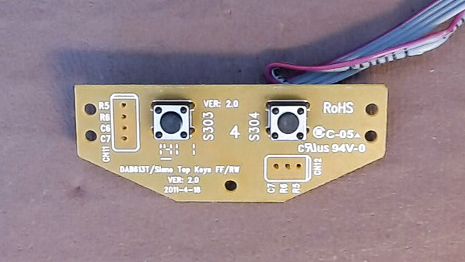
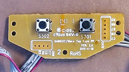
The CD player looks more useful. There are five switches and a USB socket. The switches terminate on a small plug which might connect direct to the GPIO connection on the RiPi, one pin for each switch. Unfortunately the rear of the connection to the PCB (CN10) is marked R5, R6, R7, C5, C6
- Skip Fwd/Back (S303, S304)
- Play/Pause (S301)
- Stop (S302)
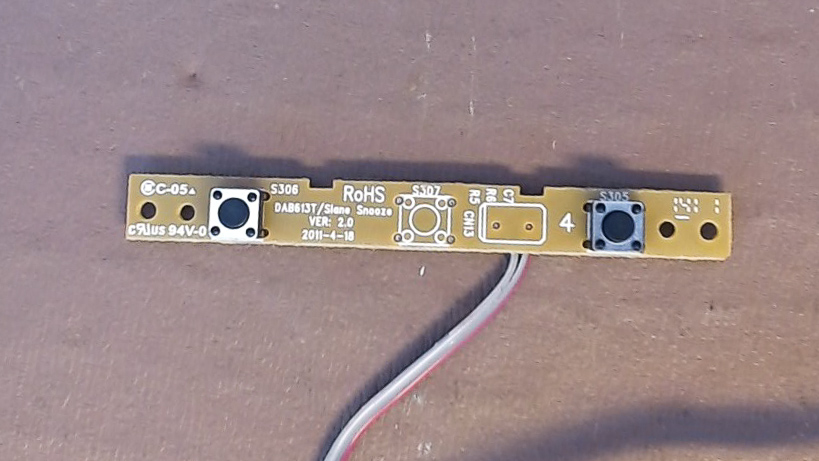
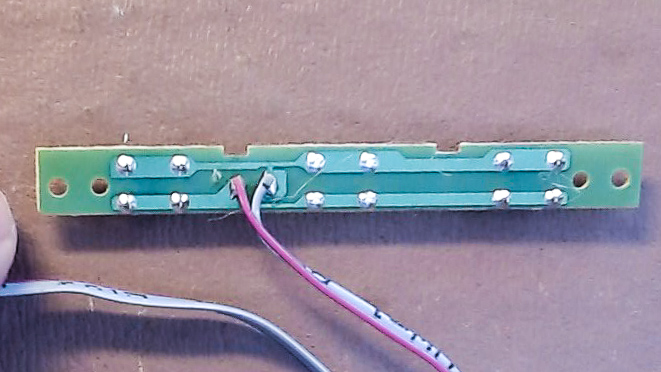
- Snoze (S305, S306)
- Lid open/closed
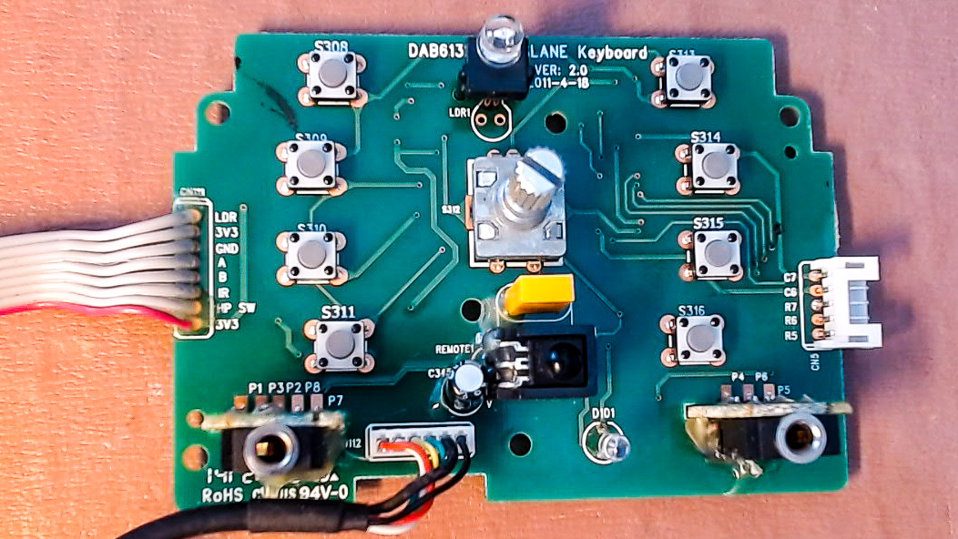
There are some cutouts for the CD lens assembly. Best bet will to cut and paint some thin MDF or acrylic and glue over the existing assembly. I will need to mount the RFID reader and possibly a display for use when selecting albums.
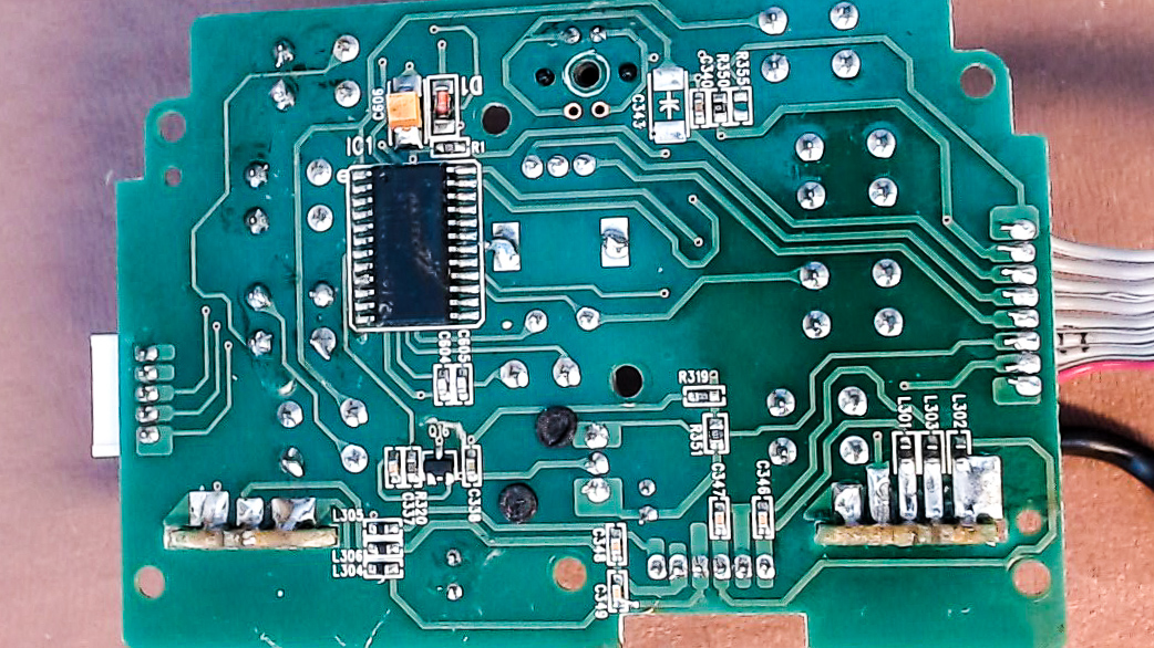
Front panel
This has two circuit boards. The first is the display (which was faulty). I hope to mount the mini LCD from the Pirat Audio board in this recess. The old PCB may be useful for the mounting.
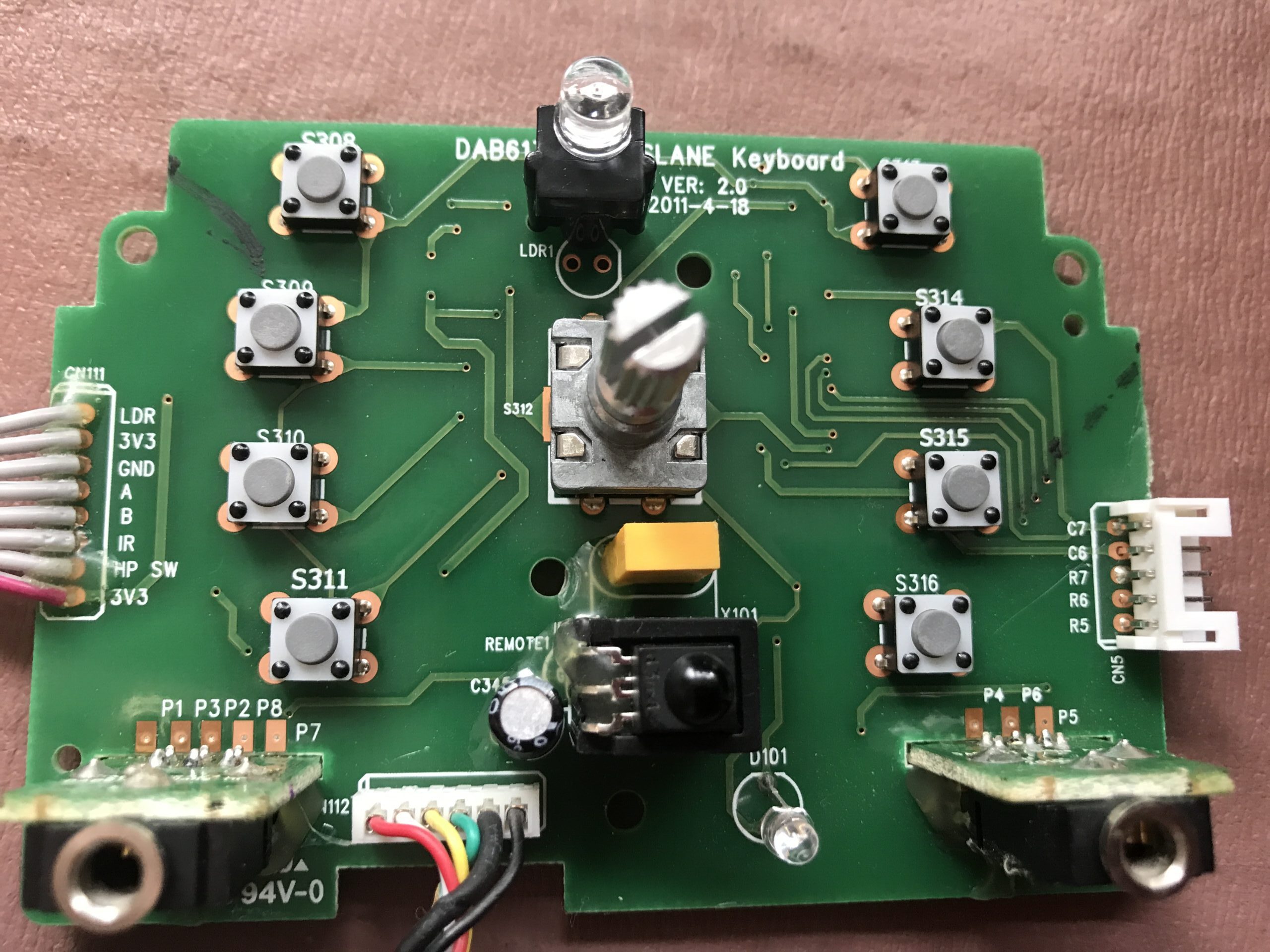
The main board has is a DIL chip – I think it says Holtek HT6222 . This is an IR decoder/encoder for the IR remote. Other useful components are:
- Two stereo audio jack plugs (with their own connector)
- 8 press switches
- Rotary Encoder with switches for both rotation and press.
- LDR for detecting ambient light level
- IR detector for the remote control
- LED power light or similar
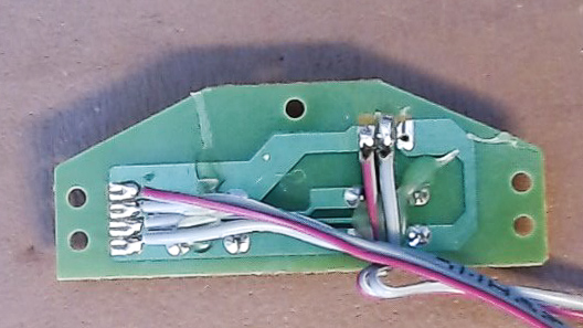
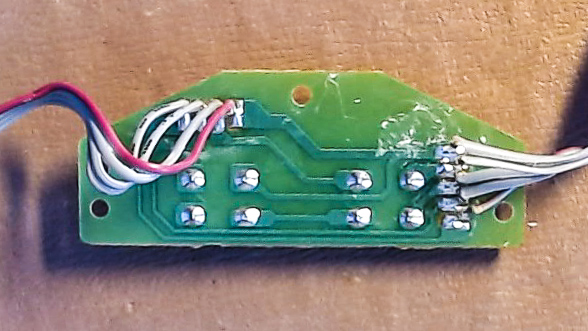
There are also a number of small inductors for the audio in/out connectors, and a few other small resistors and capacitors. Doing the best I can to trace out the circuit shows the three connection blocks:
|
CN111 to main PCB 1 LDR – Light dependent resistor |
CN5 to top lid. 1 C7 – ?? Perhaps a 3 x 2 matrix with switch information. |
Analog Audio to main PCB. Headphones out & Line Input (3 wires each) |
So the puzzle is how do you read 9 switches with just a few wires. It seems to many for a simple keyboard matrix. This page explains how a keyboard matrix works. I guess the labels C6, C7, R5, R6, R7 on connector CN5 might relate to rows and colums in a 3×2 matrix. Problem is this only covers 6 switches and I have 8.
There are various ways, this page explains how a keyboard matrix works. I guess the labels C6, C7, R5, R6, R7 on connector CN5 might relate to rows and colums in a 3×2 matrix which would give 6 switches The page also shows how, with a couple of diodes it is possible to scan a larger number of switches, but I cant see any likely looking diodes on the circuit. I guess its possible the DIL circuit is doing some thing. I will have to park this for the moment although I need to sort it to understand how to use the rotary encoder (unless its on the A/B connectors on the other connector).
Now I understand. The switches for a keyboard matrix which is decoded by the Holtek chip and sends the codes back via the IR connection to the main board. I now have two routes forward:
- Scrap the PCBs and start afresh. With luck I could cut some 0.1″ vero board to the same shape and mount the rotary encoder and any switches I need on it. I can then connect as I wish to the RiPi. Doing some rough tests it looks like the PCB is laid out on a 0.1″ or 0.05″ matrix. I can work with the former.
- Try to figure out the protocol on the ‘IR’ pin and see if I can decode it on the RiPi. The Holtek documentation describes the encoding at a very low level, but not sure if it is IR modulated or how it works.
I have a BitScope signa analyser I have been longing to play with. Time for some hacking…
Found this python library for RP. May have a go as it works with any GPIO pin. If not I can access the rotary encoder pins and butcher the boards on the top without needing to do any messy carpentry.
Hardware Design
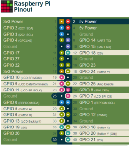
Time to staret thinking about hardware. First pin allocation for the RPi. This site https://pinout.xyz/# gives detaied info on the default pinout for various accessories.
 |
 |
Try to reuse the old ribbon cable connectors, but what type are they. They appear to be 1.27mm pitch and pins about 0.5mm square. Looks like this range. I need the following PCB sockets:
Front Pannel:
- CN5 – 5 pin x 1
- CN111 – 8 pin x 1
Pirate Audio Board
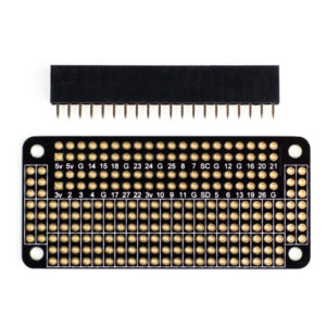
This has a 40 pin RiPi female header. I only actually need 10 pins.
CD Tray
1 off x 2 pin (Cover switch)
1 off x 5 pin (Play controls)
1 off x 4 pin (USB socket)
Need to think aboput how it goes together. All in one would add RPi male with extra long pins. I can then mount Audio board direct toi the Pi, but have a gap between where I could solder wires to the switches.
If it makes life easier I could use the right angled version instead.
Some options to think about:
‘Butterfly’ hat. Allows the 40 way connector to be split between two devices. There is also a giant butterfly that splits between 4 devices, but I dont need that. I have only seen it at Pihut.
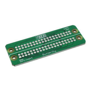
This looks just the job for wiring up the CD board and front panel.
Will need to mount some 0.1″ sockets on the prototyping board and put new terminals on the exiting ribbon. Cant work with 0.05″ pitch connectors so will have to make some leads up. Use JST 0.1″ connectors. Get a kit.
Crimping pliers from PiHut as Pimoroni are expensive. Its important to get the correct crimp. My existing ones from Lidl wont go small enough.
- PiHut Mini/Micro crimp tool – £41.50
- PiMoroni Crimp Tool £48.00