Raspberry pi weather stations

Weather station playing up has to rebuild, but found Weewx 5 has some breaking changes and world has moved on so here goes.

NB Weewx can be installed

10 Feb 2024. Weewx 5.0.2

1) Burn images Raspberry pi Legacy 32 bit lite.023-12-05 for headless operation, then install updates and Nginx.

pi@PiWeewx:~ $ sudo apt update
....
pi@PiWeewx:~ $ sudo apt full-upgrade
...
pi@PiWeewx:~ $ sudo apt remove apache2
...
pi@PiWeewx:~ $ sudo apt install nginx
...
pi@PiWeewx:~ $ sudo systemctl start nginx

### Check webserver is running.

Install Weewx. Instructions here.

# 1st time only allow apt to see weewx
sudo apt install -y wget gnupg
# NB Bug workaround: You may need to use the keys-old.html
wget -qO - https://weewx.com/keys.html | \
    sudo gpg --dearmor --output /etc/apt/trusted.gpg.d/weewx.gpg
 echo "deb [arch=all] https://weewx.com/apt/python3 buster main" | \
    sudo tee /etc/apt/sources.list.d/weewx.list

## Install Weewx 
sudo apt update
sudo apt install weewx

Install SDR extension for Weewx. This is a bit undocumented at present so some experimentation gives:.

pi@PiWeewx:~ $ sudo systemctl stop weewx
pi@PiWeewx:~ $ wget -O weewx-sdr.zip https://github.com/matthewwall/weewx-sdr/archive/master.zip
pi@PiWeewx:~ $ sudo weectl extension install weewx-sdr.zip
...
## Install drivers
pi@PiWeewx:~ $ sudo apt-get install rtl-433
...
## Free up the USB port
sudo rmmod rtl2832_sdr dvb_usb_rtl28xxu rtl2832
...
# Later you will need the Vendor ID and product ID for USB stick
# With USB stick inserted the command is lsusb -v
pi@PiWeewx:$> lsusb -v
Bus 001 Device 002: ID 0bda:2838 Realtek Semiconductor Corp. RTL2838 
DVB-T
...
idVendor 0x0bda Realtek Semiconductor Corp.
idProduct 0x2838 RTL2838 DVB-T
...
pi@PiWeewx:sudo rtl_433
_ _ _ _ _ _ _ _ _ _ _ _ _ _ _ _ _ _ _ _ _ _ _
time : 2024-02-13 16:48:08 brand : OS
model : Oregon-PCR800 House Code: 9
Channel : 0 Battery : 0 Rain Rate : 0.0 in/h
Total Rain: 6.2 in
_ _ _ _ _ _ _ _ _ _ _ _ _ _ _ _ _ _ _ _ _ _ _
time : 2024-02-13 16:48:11 brand : OS
model : Oregon-THGR810 House Code: 176
Channel : 1 Battery : 1 Celsius : 17.30 C
Humidity : 60 %
_ _ _ _ _ _ _ _ _ _ _ _ _ _ _ _ _ _ _ _ _ _ _
time : 2024-02-13 16:48:55 brand : OS
model : Oregon-PCR800 House Code: 9
Channel : 0 Battery : 0 Rain Rate : 0.0 in/h Total Rain: 6.2 in
_ _ _ _ _ _ _ _ _ _ _ _ _ _ _ _ _ _ _ _ _ _ _
time : 2024-02-13 16:49:04 brand : OS
model : Oregon-THGR810 House Code: 176
Channel : 1 Battery : 1 Celsius : 17.30 C Humidity : 60 %
_ _ _ _ _ _ _ _ _ _ _ _ _ _ _ _ _ _ _ _ _ _ _
time : 2024-02-13 16:49:42 brand : OS
model : Oregon-PCR800 House Code: 9
Channel : 0 Battery : 0 Rain Rate : 0.0 in/h Total Rain: 6.2 in
_ _ _ _ _ _ _ _ _ _ _ _ _ _ _ _ _ _ _ _ _ _ _ _
time : 2024-02-13 16:49:57 brand : OS
model : Oregon-THGR810 House Code: 176
Channel : 1 Battery : 1 Celsius : 17.30 C Humidity : 60 %

Run sdr.py to examine parsed output:

pi@PiWeewx:$ cd /etc/weewx
pi@PiWeewx:$ sudo PYTHONPATH=/usr/share/weewx python bin/user/sdr.py --cmd="rtl_433 -M utc -F json"

# If using USB stick you may need to give the user weewx permission to accesss the USB port

sudo usermod -aG plugdev weewx 

Now the BME280 drivers. First activate the I2C and spi interfaces:

     pi@PiWeewx:~ $sudo raspi-config
     # Select interface options->I2C->Yes
     # Select interface options->SPI->Yes
     # Reboot computer
     sudo reboot.

You may need to install pip, the python package installer before you can install the BME drivers.:

pi@PiWeewx:~ $ sudo apt install python3-pip


Create a driver for LCD1602 display

Need to create a Mopidy extension to drive the LCD1602 display. This will be based on the Pirate Audio PiDi display. The relevant folders are located under /usr/local/lib/python3.9/disp-packages

/usr/local/lib/python3.9/disp-packages
   |_/mopidy-pidi
   |_/pidi_display_pil
   |_/pidi_display_st7789
   |_/ST7789

Configuration is via the pidi section of mopidi.conf:

...
[pidi]
enabled = true
display = st7789
rotation = 90
...

mopidy-pidi

  • Defines the extension for mopidy.
  • Reads and verifies entries in mopidy.conf
  • Creates class PiDiFrontend that adds callbacks for various Mopidy events, like playlist_changed etc.
  • Implements class PiDi that contains an instance of the display defined in mopidy.config
  • Callbacks from mopidy are passed to the display object.

pidi-display-pil

This is a plugin for a Tk display. Used in the st7789 to do all the layout for the overlay and artwork. Not needed for the text display.

pidi_display_st7789

This is the display plugin for the st7789. This implements the interface required by the pidi display architecture (defined in PiDi Plugin.py) and adds a few extra arguments that can be added to the config file.

ST7789

This is the Adafruit driver for the ST7789 display. Handles all the low level stuff. Imports RP.GPIO to deal with the actual hardware.

New/Replacement modules

mopidy-txtdi

  • Defines the extension for mopidy.
  • Reads and verifies entries in mopidy.conf
  • Creates class TxtDiFrontend that adds callbacks for various Mopidy events, like playlist_changed etc.
  • Implements class TxtDi that contains an instance of the display defined in mopidy.config
  • Callbacks from mopidy are passed to the display object.

txtdi-display-RGB1620

RGB1620

This is Adafruit driver for the RGD1620 display.

Making it work

Mopidy crib  sheet
==================

Location of files: /usr/local/lib/python3.9/dist-packages/...

Stop/Start/Interactive
======================
As a service:
	sudo systemctl enable mopidy
	sudo systemctl stop mopidy
	sudo systemctl start mopidy
	sudo systemctl restart mopidy
	sudo systemctl status mopidy

At a terminal:
	mopidy
	mopidy --help
	
<ctrl>-C to exit.
Config file read from ~/.config/mopidy/mopidy.conf
Debug info goes to terminal


Fix to make files easy to edit:
    sudo su
    find /etc/weewx -exec chmod o+w {} \;
    find /var/www/html -exec chmod o+w {} \;

Making a development evvironment for Mopidy.

We will be using virtualenvwrapper to create a workspace in a a virtual environment when working on mopidy. This isolates anything we do from the normal python environment. First of all make sure modpidy is not running:

sudo systemctl stop mopidy

Now install virtualenvwrapper software:

sudo pip install virtualenvwrapper

To complete the install you will need to edit your .bashrc file and reload it to add the definitions to your default environment.

nano ~/.bashrc

# Add these 3 lines at the end of .bashrc and save
    export WORKON_HOME=~/Envs
    mkdir -p $WORKON_HOME
    source /usr/local/bin/virtualenvwrapper.sh

Finally, ‘source’ the file to load the definitions to your environment (or reboot):

source ~/.bashrc

You can now install mopidy into the environment. This will make it easy

Hacking the Mopidy music player.

We will use the following hardware:

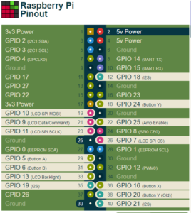
Need to check what pins are in use by various boards from pinout.xyz.

#02 5Vpower
#12 GPIO 18 I2S
#18 GPIO 24 Button (not needed)
#19 GPIO 10 LCD SPI Data
#22 GPIO 25 Amplifier enable
#23 GP10 11 LCD SPI (not needed)
#29 GPIO 7  LCD SPI CS (not needed)
#29 GPIO 5 Button A (not needed)
#31 GPIO 6 Button B (not needed)
#33 GPIO13  LCD Backlight (not needed)
#35 GPIO 19 I2S
#36 GPIO 16 Button X
#38 GPIO 20 Button Y Obsolete
#39 GPIO 21 I2S

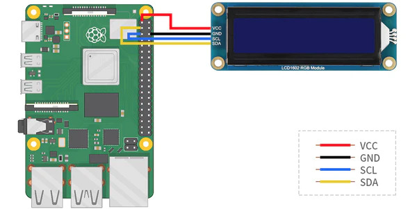
For the 16 x 2 display we need power and the I2C interface. This can support more than one device, so no problems. Here are the connections

#01 +3.3V Power #03 GP1O 02 SCL #05 GP1O 05 SCL #09 GRND Ground

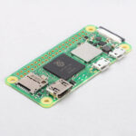
Raspberry Pi Zero wireless, Version 2Pirate audio amplifierWaveshare LCD1602 displayBreakout board for Pi ZeroHardware & speakers from Pure Chronos CD player

Raspberry Pi Zero wireless, Version 2Pirate audio amplifierWaveshare LCD1602 displayBreakout board for Pi ZeroHardware & speakers from Pure Chronos CD player

Experiments with the display

Remove Pirate Audio board.

Make a Development ENvironment

We will be using virtualenvwrapper to create a workspace in a a virtual environment when working on mopidy. This isolates anything we do from the normal python environment. First of all make sure modpidy is not running:

sudo systemctl stop mopidy

Now install virtualenvwrapper software:

sudo pip install virtualenvwrapper

To complete the install you will need to edit your .bashrc file and reload it to add the definitions to your default environment.

nano ~/.bashrc
# Add these 3 lines at the end of .bashrc and save
    export WORKON_HOME=~/Envs
    mkdir -p $WORKON_HOME
    source /usr/local/bin/virtualenvwrapper.sh

Finally, ‘source’ the file to load the definitions to your environment (or reboot):

source ~/.bashrc

Useful commands when working with virttualenvwrapper are:

Create an environment for working on mopidy

You are now ready to create your environment for working on mopidy. You need to create a directory to work in and check which version of python you are running with and where it is located. Start looking under /usr/bin/ . In my case its python 3.9

# Determine which version of Python you are running:
ls /usr/bin/python*
/usr/bin/python   /usr/bin/python3.9         /usr/bin/python3-config
/usr/bin/python3  /usr/bin/python3.9-config

# Create the virtual environment
mkdir ~/mopidy_dev
cd modpidy_dev
mkvirtualenv -a ~/mopidy_dev --python $(which python3.9) \
          --system-site-packages mopidy

You are now ready to start installing software into your virtual environment.

Setup & Test Pirate AUdio

On Windows PC, use the Raspberry Pi imager to burn image to MicroSd card. We need to set it up for ‘headless’ operation so, in the settings cog set the following:

  • Set hostname
  • Enable SSH
  • Set default username and password
  • Configure Wireless LAN

Note first boot takes some time because it has to arrange the file system and do other housekeeping. Reboot and then install Pirate Audio using these instructions. This makes the nessesary changes to config.txt and installs a number of useful extensions such as:

  • Mopidy – The core component for the system
  • Mopdi-PiDi display driver (we wont be using this in the final system, but its useful for testing and hacking to provide a driver for the 16 x 2 display).
  • Mopidy-Iris – Web based UI for driving the player from another computer
  • Mopidy-Raspberry-GPIO – We will be replacing this with a hacked version of Mopidy-Headless when we come to implement the controls based on the Pure Chronois hardware.

The core Mopidy installer also installs the following bundled extensions:

  • Mopidy-File
  • Mopidy-M3U
  • Mopidy-Stream
  • Mopidy-HTTP
  • Mopidy-SoftwareMixer

Here we use the Pirate Audio installer to setup Mopidy and various utilities so we can do a simple test of the system.

git clone https://github.com/pimoroni/pirate-audio
cd pirate-audio/mopidy
sudo ./install.sh
...

Use WinSCP to copy come music to your ~/Music folder. Instruct Mopidy to index the music folders.

sudo mopidyctl local scan

Reboot the system and test the installation. Using the browser on your PC, connect to iris on the RP and play some music:

http://192.168.1.20:6680/iris/

Be sure to check out /etc/mopidy/mopidy.conf. This file contains the confuration used by mopidy. The pirate audio installer configures this to define which modules load, which actions the GPIO pins implement and where the mucic folder is located. Consult the detiled documentation to see how other configurations can be achieved.

The following copmmands can be used to start/stop the Modidy service from running. See also other commands to control Mopidy:

sudo systemctl enable mopidy
sudo systemctl start mopidy
sudo systemctl stop mopidy
sudo systemctl restart mopidy 
sudo systemctl status mopidy   # Displays status & log info
mopidy --help

See this page for instructions on running mopidy from a terminal.

Populate workspace for use with Mopidy

First use the virtualenv command workon mopidy to switch to your development workspace and then clone a copy of mopidy sources from GitHub. Use the git branch command to check you are on a development branch. Finally cd to the mopidy folder and use the install script. NB There is no need to ‘sudo’ the commands this time as you are working in your own home directory.

sudo systemctl stop mopidy
..
workon mopidy
pwd
/home/pi/mopidy_dev
git clone https://github.com/mopidy/mopidy.git
...
cd ~/mopidy-dev/mopidy/
pwd
/home/pi/mopidy_dev/mopidy
...
git branch
* develop
pip install --upgrade --editable .

Next we’ll want to run Mopidy from the Git repo. There’s two reasons for this: first of all, it lets you easily change the source code, restart Mopidy, and see the change take effect. Second, it’s a convenient way to keep at the bleeding edge, testing the latest developments in Mopidy itself or test some extension against the latest Mopidy changes.

Assuming you’re still inside the Git repo, use pip to install Mopidy from the Git repo in an “editable” form:

pip install --upgrade --editable .

If the above command fails with AttributeError: install_layout please refer to #2037 . Try using:

export SETUPTOOLS_USE_DISTUTILS=stdlib
pip install --upgrade --editable .

You now have an editable version of mopidy you can tinker with. You may like to test it by starting from the command line with the mopidy or mopidy--verbose option to see the full gory detail, or omit to see the shorter information (including which config file it is using).

mopidy
INFO     2022-07-19 16:29:58,577 [1632:MainThread] mopidy.__main__
  Starting Mopidy 3.3.0
INFO     2022-07-19 16:30:01,056 [1632:MainThread] mopidy.config
  Loading config from builtin defaults
INFO     2022-07-19 16:30:01,147 [1632:MainThread] mopidy.config
  Loading config from file:///home/pi/.config/mopidy/mopidy.conf
INFO     2022-07-19 16:30:01,170 [1632:MainThread] mopidy.config
  Loading config from command line options
INFO     2022-07-19 16:30:05,417 [1632:MainThread] mopidy.__main__
  Enabled extensions: iris, m3u, softwaremixer, http, pidi, file, local, stream
INFO     2022-07-19 16:30:05,421 [1632:MainThread] mopidy.__main__
  Disabled extensions: spotify, raspberry-gpio
WARNING  2022-07-19 16:30:05,428 [1632:MainThread] mopidy.__main__
  Found spotify configuration errors. The extension has been automatically disabled:
WARNING  2022-07-19 16:30:05,435 [1632:MainThread] mopidy.__main__
    spotify/username must be set.
WARNING  2022-07-19 16:30:05,440 [1632:MainThread] mopidy.__main__
    spotify/password must be set.
WARNING  2022-07-19 16:30:05,445 [1632:MainThread] mopidy.__main__
    spotify/client_id must be set.
WARNING  2022-07-19 16:30:05,451 [1632:MainThread] mopidy.__main__
    spotify/client_secret must be set.
WARNING  2022-07-19 16:30:05,458 [1632:MainThread] mopidy.__main__
  Please fix the extension configuration errors or disable the extensions to silence these messages.
INFO     2022-07-19 16:30:07,010 [1632:MainThread] mopidy.commands
  Starting Mopidy mixer: SoftwareMixer
INFO     2022-07-19 16:30:07,037 [1632:MainThread] mopidy.commands
  Starting Mopidy audio
INFO     2022-07-19 16:30:07,076 [1632:MainThread] mopidy.commands
  Starting Mopidy backends: LocalBackend, FileBackend, M3UBackend, StreamBackend
INFO     2022-07-19 16:30:07,225 [1632:Audio-2] mopidy.audio.actor
  Audio output set to "autoaudiosink"
INFO     2022-07-19 16:30:07,565 [1632:MainThread] mopidy.commands
  Starting Mopidy core
INFO     2022-07-19 16:30:07,715 [1632:MainThread] mopidy.commands
  Starting Mopidy frontends: PiDiFrontend, IrisFrontend, HttpFrontend
INFO     2022-07-19 16:30:07,743 [1632:IrisFrontend-9] mopidy_iris.core
  Starting Iris 3.64.0
INFO     2022-07-19 16:30:07,787 [1632:HttpFrontend-11] mopidy.http.actor
  HTTP server running at [::ffff:127.0.0.1]:6680
INFO     2022-07-19 16:30:07,791 [1632:MainThread] mopidy.commands
  Starting GLib mainloop

You will need to use Ctrl+C to stop it running.

Connect up display:

On your PC, download the Waveshare demo code and extract. Then copy across to the RPi to ~/LCD1602/. You will need to enable the I2C interface on the RPi:

sudo raspi-config
# Then Choose Interfacing Options -> I2C -> Yes  to enable I2C interface

You can now test the display by running one of the demo programs:

python Choose_Color.py 

Note the module RGB1602.py will need to be included in your programs.

Download the demo code from 
cd ~
wget https://www.waveshare.com/wiki/File:LCD1602-RGB-Module-demo.zip
cd ~/LCD1602-RGB-Module-demo/Raspberry
sudo chmod 777 *
sudo python Choose_Color.py 
sudo python Discoloration.py 

Libre Office and Ordinal Numbers

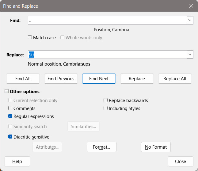
I have a love/hate relationship with Libre Office Writer. I’m currently typesettings a book with lots of dates and footnotes. One feature of Writer is its ‘Autocorrect’ option that converts ordinal numbers so that, typing something like ’29th’ gets converted into into ’29th ‘. Many people would think this fantistic, but anal retentives like me whine that using its implementation of superscripts for the ‘th’ is rather naff. When printed the superscript variant looks too thin and spidery. Its implemented by scaling and raising the characters. Thanks to the wonders of OpenType, many type faces now include special variants tor superscript and subscript forms. The problem is hwo to get them into the document. In my case there are over 300 instances in the document that need changing. Rather than doing it by hand I used the Find/Replace dialog. You need to use regular expressions to search for instances of two adjacent characters formatted with the ‘Position’ attribute and replace them with the same text set in the font variant ‘Cambria:sups’. The ‘..’ pattern means any two characters’, the replacement string is $0 which means the matched text. The dialog looks like this:

I have specified find string to include both a position attribute as well as the Cambria font (I have other fonts in the document that dont have superscript forms). Unfortunately the font attribute seems to be ignoted by Libre Office.

The result looks like this. The upper version is the default superscript, the lower is using the proper superscript variants. Looks much better when printed.

What I would really like is for Libre Office to have a proper search and replace option so I could use a character style.

Hacking a Mopidy media player.

The aim is to have a number of buttons that can control the player. Main functions are:

  1. Stop/Start player.
  2. Next/Previous track
  3. Volume up/Down
  4. Select Genre. The RFID tag will select the genre.
  5. Scroll through Albums from those available.
  6. Play an album.
  7. Control display
  8. … Lots more.

Pirate Audio software gives a start, but I need to reverse engineer it to see how it works. First question is where is it located? How is it built? There is a lot of good documentation on the Mopidy site, but lacks the file locations I need to get my head round.

Only one hit for sudo find / -name rotencoder.py shows this location. Here are the relevant folders:

/usr/local/lib/python3.9/dist-packages/mopidy
/usr/local/lib/python3.9/dist-packages/mopidy_raspberry_gpio/
/usr/local/lib/python3.9/dist-packages/mopidy_iris 
/usr/local/lib/python3.9/dist-packages/mopidy_local
/usr/local/lib/python3.9/dist-packages/mopidy_pidi 
/usr/local/lib/python3.9/dist-packages/musicbrainzngs
/usr/local/lib/python3.9/dist-packages/pidi_display_pil
/usr/local/lib/python3.9/dist-packages/pidi_display_st7789
/usr/local/lib/python3.9/dist-packages/uritools

Make the files easier to remote edit:

sudo su

find /etc/mopidy -exec chmod o+w {} \;

find /usr/local/lib/python3.9/dist-packages/mopidy_raspberry_gpio/  -exec chmod o+w {} \;

find /usr/local/lib/python3.9/dist-packages/mopidy_iris   -exec chmod o+w {} \;

find /usr/local/lib/python3.9/dist-packages/mopidy_local /usr/local/lib/python3.9 -exec chmod o+w {} \;

find /usr/locallib/python3.9/dist-packages/mopidy_pidi -exec chmod o+w {} \;

find /usr/local/lib/python3.9/dist-packages/musicbrainzngs  -exec chmod o+w {} \;

find /usr/local/lib/python3.9/dist-packages/pidi_display_pil  -exec chmod o+w {} \;

find /usr/local/lib/python3.9/dist-packages/pidi_display_st7789  -exec chmod o+w {} \;

find /usr/localfind /lib/python3.9/dist-packages/uritools -exec chmod o+w {} \;

find /etc/mopidy -exec chmod o+w {} \;

Looking at the Pirate Audio installer script. It does the following:

  • Modify /etc/modipy/modpi.cont
  • Installs the following python libraries:
    • python3-rpi.gpio- Extensions for GPIO
    • python3-spidev- Extensions for the SPI interface used by display
    • python3-pip- PIP installer
    • python3-pil- Package installer for Python.
    • python3-numpy- Package for dealing with arrays.
    • libopenjp2-7 – JPEG and JPG200 image library.
    • Enables SPI interface
    • Modifies config.txt for GPIO pins and the DAC.
    • Installs Mopidy and spotify plugins.
    • Installs and updates modpi_iris for image display.
    • Installs plugins for Pirate Audio:
      • Mopidy-PiDi
      • Mopidy-Local
      • pidi-display-pil
      • pidi-display-st7789
      • mopidy-raspberry-gpio
      • mopidy_iris
    • Modifies the mopidy config file to configure the various modules:
      • raspberry-gpio – define pin mappings
      • file – specify where to find music files
      • pidi – specify display controller
      • mpd – music player daemon on local machine.
      • http – web server interface
      • audio – output audio device & volume
      • spotify – connection details

So now I start to see what is needed. I need:

  • mopidy_raspberry_gpio
    Replace with mopidy_Chronos to map the IR to mopidy commands .
  • modipy local


Display is handled


IR detection with Raspberry Pi

Previous post showed how I stripped down a Pure Chronos CD/Radio and showed how the various buttons on the chassis were transmitted to the motherboard as a pseudo IR signal. Now its time to decode the signal on the Raspberry PI.

This article seems to be reasonably up to date:

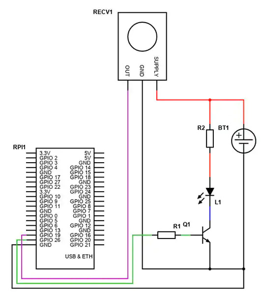
https://www.digikey.co.uk/en/maker/blogs/2021/how-to-send-and-receive-ir-signals-with-a-raspberry-pi

Here is the circuit they use:

First step is to edit /boot/config.txt to specify the IO pins I am reading IR signal on GPIO pin 19.

dtoverlay=gpio-ir,gpio_pin=19 # for receiving data
##dtoverlay=gpio-ir-tx,gpio_pin=26 # for sending commands

Reboot:

sudo reboot now

Install some helper libraries:

sudo apt update
sudo apt install ir-keytable

Test:
This command will read IR reciever and print parsed commands.

sudo ir-keytable -c -p all -t

Investigate if this fails when you send some signals. After fixing incorrect wiring, I get something like this:

pi@raspberrypiMP3:~ $ sudo ir-keytable -c -p all -t
Old keytable cleared
Protocols changed to unknown other lirc rc-5 rc-5-sz jvc sony nec sanyo mce_kbd rc-6 sharp xmp cec imon rc-mm
Loaded BPF protocol xbox-dvd
Testing events. Please, press CTRL-C to abort.
246.860112: lirc protocol(nec): scancode = 0x8099
246.860168: event type EV_MSC(0x04): scancode = 0x8099
246.860168: event type EV_SYN(0x00).
246.920145: lirc protocol(nec): scancode = 0x8099 repeat
246.920207: event type EV_MSC(0x04): scancode = 0x8099

Yea, I can now read the various button presses from the Chronos chassis and read them with the RP. I could go further ans install the main lirc library, but enough for now. Time to reassemble the hardware and try to hack the music player software. Not sure if I will require LIRC as I dont need to translate the keycodes, but it may be helpful to get the data into the player software.

Install lirc for the main library:

sudo apt install lirc


Edit the configuration file so set the sensor up as a device:

sudo nano /etc/lirc/lirc_options.conf
... and add...
driver = default
device = /dev/lirc0

Reboot and test:

sudo systemctl stop lircd.service
sudo mode2 -d /dev/lirc0

… and so it goes on…

A Music Player for when I am Old

Introduction

The plan is to make a box to play music from my music library. It must be incredibly simple to use (no buttons), but most of all it needs a VOLUME control.

Desing based an old Chronos CD/Radio alarm, but replace all electronics lot with a Raspberry pi and use some RFID tags – more later.

This is what the device looks like at the start:

If all goes well it will look much the same at the end, but with a more snazzy display.

The plan is to rip the guts out (except for the speakers) and hide a Raspberry Pi inside. To use, pop open the CD lid, insert a RFID tag to select a folder full of music, eg: Blues/Classical/Pop/Vocal etc. The folder RFID tag will of corse be concealed in a vinyl record like one of these.

Its all controlled by the BIG SILVER KNOB on the front. Load a place mat and an folder full of appropriate music is selected at random. Close the lid and its starts playing. Turn the BSG with the lid open and it starts to scroll through available albums. Close the lid and the knob controls the volume. So simple, what could go wrong….

Components

It looks like its important to use the version 2 for the raspberry pi zero because it has a bit more CPU than the original version. Wifi will be on and the pi running ‘headless’. When it requires attention I can connect in over the wifi. The Pirate Radio Amp is powered by the RPi which simplifies things a bit. Its a Class D amplifier which makes it very efficient. Its supposed to be used with 8 ohm speakers and the old speakers are 6 ohm. I doubt it matters much. Its the power handeling that counts (unless you want to blow them up!). The Pirate Audio board includes a display and four buttons. The display is a bit smaller than I would like, but may fit in the front pannel display above the BIG SILVER KNOB.

The Pirate Audio board also includes four buttons. By default they are Play/Pause/Volume Up/Down but can be reconfigured.  I will need to figure out how to use the BIG SILVER KNOB to control the system.

I also have a small 3.5″ display. I may fit it inside the CD compartment to help scroll through the albums. Not sure at present if it is possible to have two boards connected to the RPi at the same time.

Software

The preferred player software looks like Mopidy . Its built for lots fo versions of Unix. We need the Debian build for Raspberian.

This shows an add on to configure a rotary encoder for the volume control. The project has excellent documentation and looks like it will take me as far as I want to go.

Testing Pirate Audio

  1. Burn SD card for RiPi using RiPi recomended online imager. Use ‘Raspberry Pi OS ‘Lite’ 32 bit image since I will be running headless.  Click the settings cog and set the following options:
    1. Hostname: RaspberryPiMP3
    2. Enable SSH/Use Password
    3. Set Username & Password: pi & password of your choice
    4. Configure Wireless LAN: add details of your WiFi.
    5. Confirm you have correct locale and country for the keyboard, WiFi and other settings.
    6. Wait for the image to download and the card to be programmed.
  2. Insert SD card and test RiPi boots (green light by power connector shows).
  3. On your WiFi router look for the IP address of your RiPi. It may appear as ‘Raspberry Pi Foundation’. If you cant find it try this post.

You can now try connecting to the RiPi.

  1. On your Windows computer install and start Putty. Type in the IP address and press connect. You will first be asked something about keys. This is a security precaution. When you first connect Putty gets a digital fingerprint from the RiPi and stores it. You dont see this on subsequent logins. You should see a black console window asking you to log in. Note this is NOT the Windows consule, you are connecting to the RiPi command line. You may like to save the connection details for future use.
  2. On your Windows computer install and start WinScp. This allows you to browse the file system on the RiPi and transfer files between it and your Windows computer. Your ‘home’ folder on the RiPi is /home/pi. You can freely create and delete files in this folder. Try creating a folder ‘music’ and copy some MP3 files into it. Note there is a button to allow files to be transferred in the background.

When the files have transferred, shutdown the RiPi and connect the Pirate Audio board and some speakers. Be careful you dont damage the display when you attach the edge connector. Time to set up the Pirate Audio board.

  • Use Putty to connect to the RiPi.
  • Follow these instructions to get the software up and running. Note that if you want to copy text from Windows to the console window, you can copy it to the Windows clipboard and then a right click on the Putty window will automatically paste it.
  •  


Hardware

The old CD player is quite simple to dismantle. Undo the screws on the bottom and the top lifts off quite easily. The only slight sticking point is the screws to remove the front panel and speakers are at the bottom of a deep recess. I needed some blue tack, a torch and screwdriver. Once in bits its useful to review what to save.

The two speakers are fine. Nice and chunky good quality units.

The main board is not much use. I had hoped to use the amplifier but its all digital and can’t be changed. I will keep the board because I can trace around it to make a replacement motherboard.

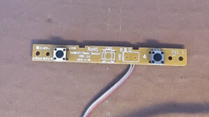
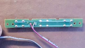
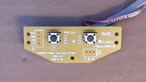
Top Panel – CD player

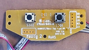
The CD player looks more useful. There are five switches and a USB socket. The switches terminate on a small plug which might connect direct to the GPIO connection on the RiPi, one pin for each switch. Unfortunately the rear of the connection to the PCB (CN10) is marked R5, R6, R7, C5, C6

  • Skip Fwd/Back (S303, S304)
  • Play/Pause (S301)
  • Stop (S302)
  • Snoze (S305, S306)
  • Lid open/closed

There are some cutouts for the CD lens assembly. Best bet will to cut and paint some thin MDF or acrylic and glue over the existing assembly. I will need to mount the RFID reader and possibly a display for use when selecting albums.

Front panel

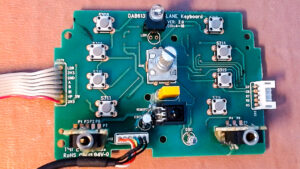
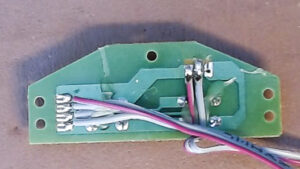
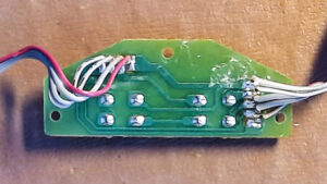
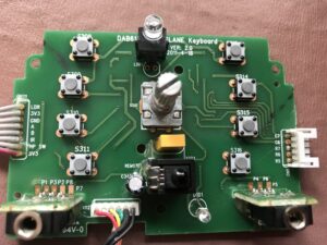
This has two circuit boards. The first is the display (which was faulty). I hope to mount the mini LCD from the Pirat Audio board in this recess. The old PCB may be useful for the mounting.

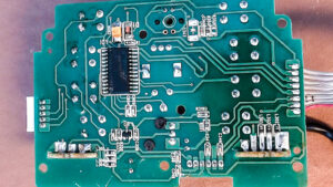
The main board has is a DIL chip – I think it says Holtek HT6222 . This is an IR decoder/encoder for the IR remote. Other useful components are:

  • Two stereo audio jack plugs (with their own connector)
  • 8 press switches
  • Rotary Encoder with switches for both rotation and press.
  • LDR for detecting ambient light level
  • IR detector for the remote control
  • LED power light or similar

There are also a number of small inductors for the audio in/out connectors, and a few other small resistors and capacitors. Doing the best I can to trace out the circuit shows the three connection blocks:

CN111 to main PCB

1  LDR – Light dependent resistor
2  3V3 – Supply
3  GND– Ground
4  A – Rotary Encoder ‘A’
5  B- Rotary Encoder ‘A’
6 IR  – Infra red outout.
7  HP SW – Headphone Switch
8  3v3 – Supply?

CN5 to top lid.

1  C7 – ??
2  C6 – ??
3  R7 – ??
4 R6 – ??
5 R5 – ??

Perhaps a 3 x 2 matrix with switch information.

Analog Audio to main PCB.

Headphones out & Line Input (3 wires each)

So the puzzle is how do you read 9 switches with just a few wires. It seems to many for a simple keyboard matrix. This page explains how a keyboard matrix works. I guess the labels C6, C7, R5, R6, R7 on connector CN5 might relate to rows and colums in a 3×2 matrix. Problem is this only covers 6 switches and I have 8.

There are various ways, this page explains how a keyboard matrix works. I guess the labels C6, C7, R5, R6, R7 on connector CN5 might relate to rows and colums in a 3×2 matrix which would give 6 switches The page also shows how, with a couple of diodes it is possible to scan a larger number of switches, but I cant see any likely looking diodes on the circuit. I guess its possible the DIL circuit is doing some thing. I will have to park this for the moment although I need to sort it to understand how to use the rotary encoder (unless its on the A/B connectors on the other connector).

Now I understand. The switches for a keyboard matrix which is decoded by the Holtek chip and sends the codes back via the IR connection to the main board. I now have two routes forward:

  1. Scrap the PCBs and start afresh. With luck I could cut some 0.1″ vero board to the same shape and mount the rotary encoder and any switches I need on it. I can then connect as I wish to the RiPi. Doing some rough tests it looks like the PCB is laid out on a 0.1″ or 0.05″ matrix. I can work with the former.
  2. Try to figure out the protocol on the ‘IR’ pin and see if I can decode it on the RiPi. The Holtek documentation describes the encoding at a very low level, but not sure if it is IR modulated or how it works.

I have a BitScope signa analyser I have been longing to play with. Time for some hacking…

Found this python library for RP. May have a go as it works with any GPIO pin. If not I can access the rotary encoder pins and butcher the boards on the top without needing to do any messy carpentry.

Hardware Design

Time to staret thinking about hardware. First pin allocation for the RPi. This site https://pinout.xyz/# gives detaied info on the default pinout for various accessories.

Default pin allocation for the Pirate Audio Board
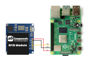
Circuit for the RFID circuit board

Try to reuse the old ribbon cable connectors, but what type are they. They appear to be 1.27mm pitch and pins about 0.5mm square. Looks like this range. I need the following PCB sockets:

Front Pannel:

  • CN5 – 5 pin x 1
  • CN111 – 8 pin x 1

Pirate Audio Board

This has a 40 pin RiPi female header.  I only actually need 10 pins.

CD Tray

1 off x 2 pin (Cover switch)
1 off x 5 pin (Play controls)
1 off x 4 pin (USB socket)

Need to think aboput how it goes together. All in one would add RPi male with extra long pins. I can then mount Audio board direct toi the Pi, but have a gap between where I could solder wires to the switches.

Male 40-pin 2×20 HAT Header

If it makes life easier I could use the right angled version instead.

Some options to think about:

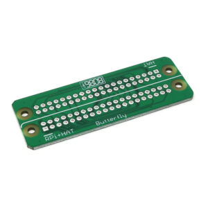
‘Butterfly’ hat. Allows the 40 way connector to be split between two devices. There is also a giant butterfly that splits between 4 devices, but I dont need that. I have only seen it at Pihut.

This looks just the job for wiring up the CD board and front panel.

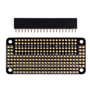
ProtoZero Raspberry Pi Zero Prototyping Board

ProtoZero Raspberry Pi Zero Prototyping Board £5 The Pi Hut.

Will need to mount some 0.1″ sockets on the prototyping board and put new terminals on the exiting ribbon. Cant work with 0.05″ pitch connectors so will have to make some leads up. Use JST 0.1″ connectors. Get a kit.

Crimping pliers from PiHut as Pimoroni are expensive. Its important to get the correct crimp. My existing ones from Lidl wont go small enough.


Call Screening with a FritzBox router

Back in the days when telephones used copper wire I used a ‘BT 8500 Advanced Callblocker’ phone to get rid of my spam. It worked very well. Anyone who called and was in my phone book was connected normally, anyone else got sent to voice mail. If they spoke, my phone rang and I could listen to the message to decide whether to pick up. Most sales calls gave up the moment they heard the answerphone. The only problem was my brother who, being a Doctor, blocked his phone number. He had to learn to wait while I accepted the call. Recently I have moved to VOIP and use  Fritz!box router which provides both analogue and direct digital connection to DECT phones. It generally works well but the is a big BUT with the analogue phone connection and the BT Advanced Call Blocker phone. Buried somewhere in the small print on the TrueCall website is the following disclaimer:

We don’t recommend that you use trueCall with VoIP adaptors.

The BT phone is based on Truecall technology and the same applies. Although the main telephone technology worked most of the time, I got strange faults. Tone dialing on IVR switchboards sometimes did not work. The time on the phone was not set automatically. The crunch came when I slipped a disk and needed an ambulance urgently. I found I could not dial 999.

I bit the bullet and purchased some Gradstream A690HX Cat-IQ 2 compatible DECT phones. They paired flawlessly with the router. The only issue was the spam calls came back. I get about 2 a week.

Not a big issue, but I have too much time on my hands and like to tinker. Despite extensive Googling the only ray of hope was with a german firm Tellows who have a product that is supposed to maintain a list of all numbers used for spamming. I was sceptical, but thought it worth a try. As expected, after 3 months the score is no calls blocked by Tellows, 25 spam calls answered by your truely.

The Fritz!Box is a very flexible beast. It supports multiple answer phones, extensive call routing and many other star features. The plan was to implement two answer phones, one with a mesage along the lines ‘Your phone number has not been recognised. If you like us to return your call please leave a message’, the second: “Hi. Its Bill and Ben. We cant come to the phone right now. Please leave a message.’ Program up the box to route the caller to the appropriate answerphone and job done.

After two days of fiddeling I had to admit defeat. Although I can implement two answer phones, I can only assign one to an incoming number. There is a fall back position. In desperation emailed the Fritz!box Support desk. They are excellent, despite being a German company, they speak perfect english and respond with one working day. The response I recieved not only stated they had passed a ‘whitelist’ feature as a new feature request, they alsosuggested a work around. Its  bit messy. I have to implement an dummy internal number and then use call diversion to set up the correct routing. Here are the detailed instructions:

Workaround:

You could configure a call diversion for “Calls from all persons in the telephone book” and divert them to a specific telephone which then will ring only if the caller is in your telephone book.

Or you could configure a dummy number like “1234567” in the FRITZ!Box. You will not receive external calls for that number, of course.

Now let all telephones react on number “1234567” but not your real numbers.

Have a call diversion for all incoming “Calls from all persons in the telephone book” and divert them to 1234567.

Now the telephones will ring on incoming calls only if the caller is listed in the telephone book because now their number “1234567” is dialed via call diversion.

For all other events have an answering machine reacting on all incoming calls (after 15sec, for example) which will let your answering machine answer all callers whose number is not listed in your telephone book.

Do not forget:

Configure your telephones not to react on “all incoming calls” or on “all telephone numbers” but to react on the number “1234567” only.

Then it will never ring – except in those cases in which the call diversion diverts the caller from the telephone book to number “1234567”.
Any other call will then exclusively answered by the answering machine (= any call from a caller who’s not listed in the telephone book).

Good luck!

Best regards from Berlin,
Michael Ellguth (AVM Support)


The Curious Case of the ‘Cure’ for Covid

As a result of lockdown boredom I became a Twitter twit. There I came across a link to an excellent article relating to drug testing. Obviously its important for drugs to be tested properly, both for efficacy and safety. Reputable publishers now require researchers to make their raw data available for indepencent analysis. The following articles show a detailed investigation into a large study to deterime how effective Ivermectin (worming pills normally used  for horces) is in treating Covid. Its a facinating insight into how detailed analysis of the data can be used to uncover poor quality research and how difficult it is to falsify results when subjected to proper scrutiny.

Ivermectin is not the only snake oil being pushed as a cure. Read here an older article  on Hydroxychloroquinine, a similary useless drug.

Its not just in medicine that it is possible to uncover fraud by careful analysis of the raw data. The Wikipedia article on ‘Bentfords Law’ gives lots of examples of the use of careful statistical analysis in detection of fraud in elections, accounting and criminal trials.

The moral of this is to be very careful you are not being blinded by science when reading armchair experts posting on Twitter. Look carefully at the credentials of the person who is posting and what their sources are.